
Installation Instructions
FEATURES
- Timer can be set to stop the engine from 1 minute to 48 hours
- Monitors the metal temperature of the engine using the ‘Easy Fit’ heat sensor
- Over temperature alarm is fully adjustable from 1 to 127 degrees Celsius
- Bypass Timer allows engine pressures to stabilize on start up (programmable from 1 to 240 seconds)
- Two stopping output configurations, suits fuel & decompression solenoids or electrical circuits
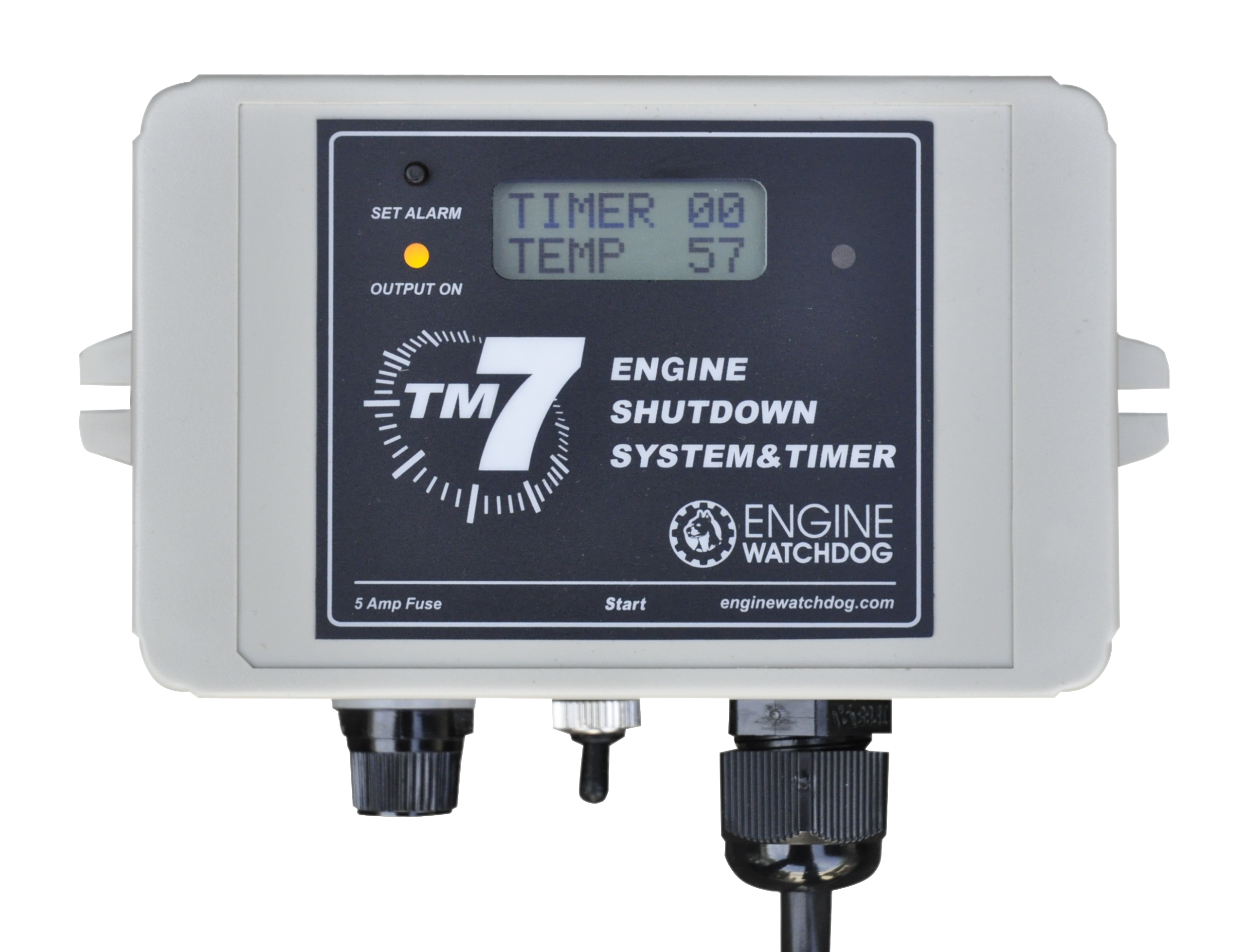
- LCD Display shows easy to read messages for all functions and alarms
- Messages display on start up to indicate what last stopped the engine
- TM7 suits ALL engine makes and models
- Suits 12 or 24 volt systems
Installation
1. Mount the unit upright with a water loop in the cabling and away from vibration, weather and direct water damage (On a post and covered, if no other support is handy).
Use the screws or silicon to mount the unit. Do not mount the unit upside down or allow it to swing around freely on its wiring.
2 Bolt the sensor firmly to the engine in a location that will reflect its working temperature, yet not exceed 125 deg. C. (avoid mounting the sensor near the exhaust manifold). Do not bend the wire at the sensor sharply.
Starting on metal part of the red sensor, wind the spiral wrap provided around the sensor cable ensuring the sensor cable is not visible. Secure the cable allowing for movement of the engine.
Secure the lead allowing for movement.
NOTE If using large cable ties, DO NOT over tighten them and crush the sensor cable.
If the sensor hole needs enlarging carefully file it, do not use a large drill or squash the sensor barrel in a vice.
3. Wire as per the diagram after selecting the correct wiring and stopping method (see yellow wire option 1 or 2)
Power wires are via the ignition switch.
Oil pressure wire goes to an oil light sender (Not a pressure gauge sender). If the engine is not equipped with an oil light sender, discard this wire or fit a sender that uses normally closed contacts with no oil pressure (standard car type).
Setting the Stop Temperature (factory set at 100c)
1. Run the engine up to working temperature and note the highest normal working temperature displayed on the TM7.
2. Next, set the Stop temperature about 7-10 degrees above the highest normal working temperature of the engine.
See point 6 in the operating guide. NOTE these settings may need revising in hot weather
Determining how much Bypass Time is required (factory set at 10 seconds)
1. As soon as the TM7 starts, press the ‘Set Alarm’ switch down. The unit will display its normal reminder messages and then stall on Manual Bypass. Measure the amount of bypass time you require and then reset the automatic bypass time as per point 7 in the operating guide.
Testing the system
- To test the Stop Temperature - Set the stop temperature lower than the normal operating temperature.
- To test the Oil Function – Ground the white wire and the unit will stop the engine.
- To test the Spare Function – Ground the black wire and the unit will stop the engine
Note. Remember to set the temperature back to the original setting.
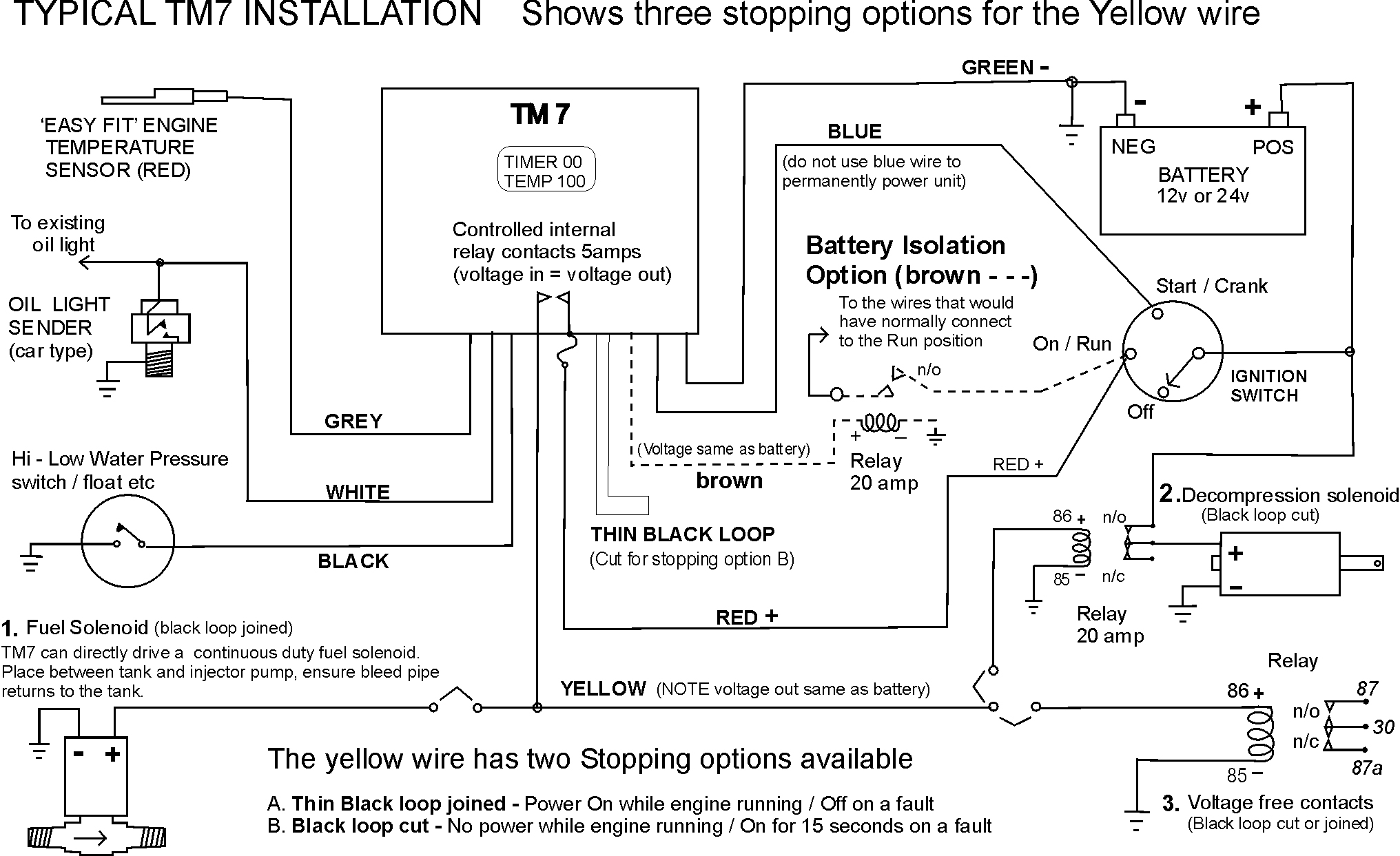
Red wire - Connect to battery positive via the ‘On / Run’ position on the ignition switch (Suits 12 or 24 volt systems)
Green wire - Connect to the battery negative
Yellow wire - Select one of three stopping options shown, if using a slave relay ensure it has the same voltage rating as the
battery. Once the yellow wire is connected then determine if the small black loop needs to be cut (See A or B)
White wire - Connect to the engines existing oil light sender, or fit a sender if required (inexpensive car type)
Black Wire - Connect to any third stopping input that requires a ground to switch (Optional)
Blue wire - This wire starts the unit without the need to press the start switch. Connect the blue wire to the
Start / Cranking position of the ignition switch (NOTE do not use this wire to permanently power the unit)
Brown wire - This wire is optional and is used to prevent the battery going flat should the operator not be returning to the
engine for an extended period after shutdown. Isolate the wires that would normally be connected to the
‘On / Run’ position of the ignition switch with a suitably rated relay (NOTE the relay must be the same voltage
rating as the battery)
black loop - Determines which switching mode the yellow wire will operate on (see diagram above for Stopping options A or B)
Trouble Shooting (also see operation guide to interpret fault messages)
Fault Finding – To fault find disconnect all wires except the red and green power wires and check each function individually
Unit will not come on. - Check the Fuse (5A Max). - Check for correct wiring (see diagram)
Unit will only power on while the start switch is pressed or while the engine is cracking and then turn off - check fuse
Fuse blows. Check wiring diagram. - Check for shorts. - Check yellow wire output is not drawing excessive current (5A max.)
Unit is intermittent or erratic. - Check connections (crimps) - Check for excessive vibration, water damage or ant invasion
Temperature is at maximum setting. – Move sensor to a cooler location (125 deg C Max)
Fuel Solenoid will not stop engine - Ensure the engine stops when the yellow wire is pulled off the positive terminal of the solenoid
Fuel Solenoid is slow to stop the engine – Ensure the injector pump bleed pipe returns to the tank.
Display reads <1 – temperature is below 0 degrees C, or Sensor cable is faulty, see Displaying Fault Condition in operating guide (point 8)
Display just reads temp at 85 - Sensor cable is faulty, see Displaying Fault Condition in operating guide (point 8)

HOME | TM7 PRODUCT DESCRIPTION | HEAT SENSOR PRODUCT DESCRIPTION
TM7 OPERATION INFORMATION | CONTACT INFORMATION